Hall Effect vs. temperature

The Hall effect is important in the investigation of the materials properties because it allows direct measurements of the free carriers concentration (with their sign) both in metals and in semiconductors.
It is also technologically important because it is the working principle of modern magnetic field sensors.
The Hall effect essentially is due to the Lorentz force F acting on each electric charge q moving with velocity v in a magnetic field B.
In metals the electric current is only due to electrons. In semiconductors instead the charge carriers may be either electrons or holes .
Let us consider a conducting bar (figure 1) immersed into a uniform magnetic field B directed along the z axis, with an electric current Ix flowing along the x axis.
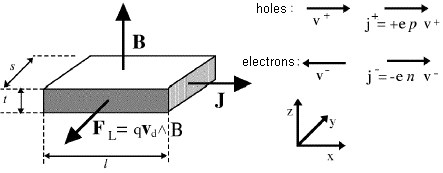
Figure 1 : Geometry of the Hall effect: the Lorentz force FL on moving charges acts along the direction shown by the arrow (independently from the charge sign)
The electrons take a drift velocity vd = -μEx proportional to the electric fiel Ex . The Lorentz force FL = q vd B, acts on electron in the negative y direction so they tend to accumulate on the sample face perpendicular to the y axis on the side facing the reader in figure 1.This charge build-up produces a potential difference VH between the two sample faces, and therefore an electric field EH ( Hall field) so that the electric force qEH cancels the Lorentz force: EH = vd B.
We may define the Hall coefficient as: RH = EH/(JB).
It may be shown that the following relation holds:
where n and p are the electrons and holes densities, respectively.
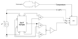
Figure 2 : Block diagram of the apparatus.
A Joule-heater wound around the aluminum base of the sample-holder, and a cold finger (with eventually a liquid nitrogen bath) placed into a steel dewar, allow temperature variations in the range 150 K – 450 K. The manually-operated heater is automatically switched-off when the temperature reaches 175 °C.
A thermocouple thermometer, linearized by a AD594 converter, allow to record the temperature values . The Hall voltage and the sample resistance may be therefore measured as functions of the temperature using an interface connected to a Personal Computer.
Seven wires are soldered to the sample with the geometry shown in figure 2.
The contacts 7 and 5 are used to measure the voltage VR=RI across the sample, to obtain the resistance R.
The contacts 1 and 4 are used to feed the current produced by a constant current generator.
A microprocessor computes the sample temperature (through a 5th order polynomialfitting the values of e.f.m. given in NIST tables) and the sample resistance (through the mneasrured value of the bias current ).
The bias current and the gains of the two channels Vh and Vr may be set from the front panel and all measured values are shown on a LCD display.
An example of the results obtained with a sample biased by a current of 10 mA in a magnetic field of 0.4 T, is shown in figure 3.
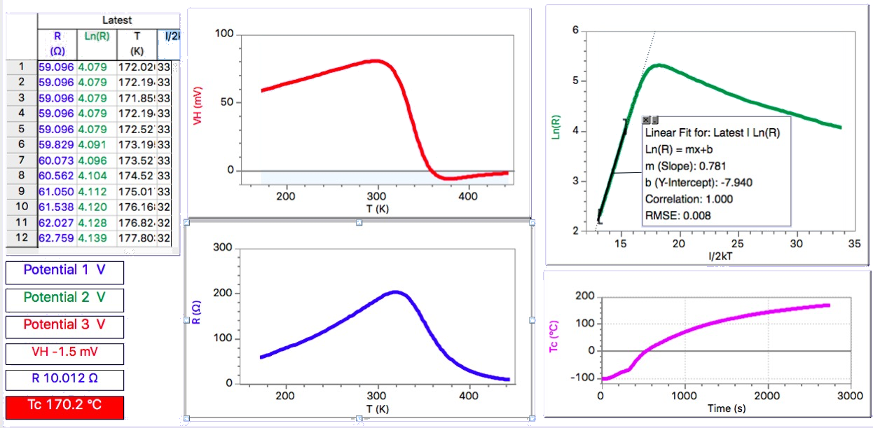
Figure 3 : VH and R vs.T
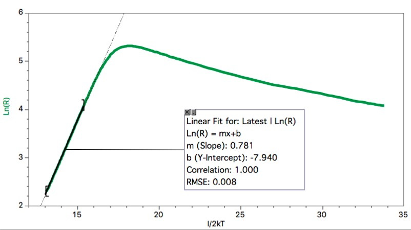 Figure 4 : Logaritm of R vs. 1/2kT.
Enclosed Gaussmeter