Innovative MicroWave Optics System

Bench length: 1m. The angle between the two 50 cm halves is variable and may be read in a large goniometer.
Frequency: 10 GHz, wavelength 3 cm, vertical polarization in
the normal working position. The polarization may be varied in a
full 90° angle.
Transmitted power: less than 5 mW.
Special innovative tubular dielectric antennas are of high directivity and minimum overall encumbrance.
Radiation safety: microwave radiation is well below established safety standards for general public environment, like ANSI C95.1-1991 of USA and NRPB-11 of United Kingdom.
The bench, the slits and the vertical holders are precision metallic or plastic elements which assure easy positioning and sliding of the various “optical” elements and accessories.
Rotating mounts: the transmitter and receiver rotate through a full 360°, an important feature for experiments in which the polarization must be studied.
Receiver: super-heterodyne, I.F.= 200 MHz, manual sensitivity control in a range of 1:20.
Output indicator: moving coil instrument. Optional: audio signal of loudness proportional to the received signal strength, useful in public or classroom demonstrations.
Power supply by a single 9 V d.c. plug-in device which may be connected to either transmitter or receiver for flexibility of installation. A cable connects the input-output power supplies of transmitter and receiver.
Demonstrations and experiments
Many
experiments, demonstrations and studies of the optical
properties of microwaves and of their interactions with matter
are allowed by this device. .
- Measurements
of absorption of
various materials: human hand, sheets of perspex,
polycarbonate, nylon, pvc, wood, cardboard, masonite,
concrete etc.
- Law of
reflection by a
conducting surface. As an example a metallic mirror supplied
as an accessory shows that a surface corrugation of a small
fraction of the wavelength does not disturb the behavior of
the reflector.
- Refraction:
sharp focusing of the microwave beam by a paraffine lens.
- Polarization:
determination of the direction of the electric field vector
by an array of close parallel (spaced less than half
wavelength) metal wires. Malus-Law (square-cosine).
- Reflection
by a dielectric surface. Transmission as a function of the
polarization and of the waveguide orientation.
Brewster angle and polarization of the reflected
and transmitted wave. Fast determination of the refractive
index of various materials at the frequiency of 10 GHz.
- Standing waves by means of a movable dielectric slab normal to the direction of propagation. Precise measurement of the wavelength.
- Young
double slit diffraction experiment with the
detection of maxima and minima in the diffraction pattern.
Measurement of the angles. By shutting up one of the slits
(for example with the hand) the signal disappears also in
the zero-th order strong maximum.
- Guided
waves. Rectangular and circular metallic waveguides
of various dimensions and their properties. Cut-off
dimensions. Polarization properties.
- Measurement of the electric field distribution inside a rectangular slotted metallic waveguide an a special diode probe. It is possible to determine the minima and maxima of the voltage standing waves of the wavelength of the electromagnetic field inside the guide, of the phase velocity which is always greater then c.
- Guided
waves. Dielectric waveguides of various materials:
PVC, acrylic, and different shapes. Strips of various width
and thickness, rods, square, tubular. Demonstration of the
absence of cut-off dimensions. Attenuation.
- Evanescent
wave in a dielectric waveguide. Measurement of the
exponential decrease of the intensity vs. the distance from
the guide by means of a diode probe, a micrometric
translation stage and a millivoltmeter.
- Fabry-Perot
interferometer and precise measurement of
wavelength. Sliding the moving mirror an high contrast of
the fringes is easily found, which allows the precise
determination of the positions of the minima and
consequently of the wavelength.
- Faraday effect. A neat demonstration of the rotation of the polarization plane, which may reach a giant 90°, by a small ferrite rod in a magnetic field of the order of tens of Gauss.
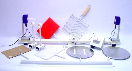
A partial set of available accessories
General view of the microwave optical bench.
Transmitter at left , receiver at right.
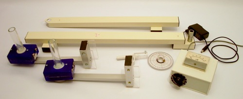
Disassembled bench
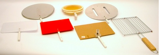
Some of the microwave reflecting, refracting, diffracting and polarizing optical components
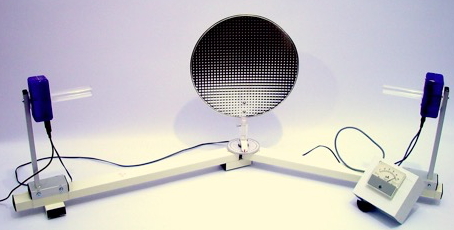
Reflection by a conducting slightly corrugated mirror.
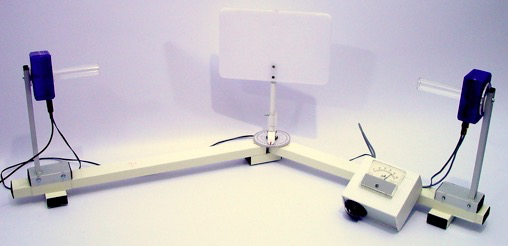
Reflection by a dielectric mirror.
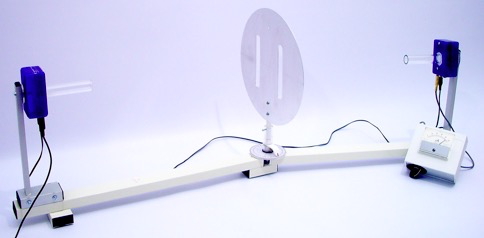
The Young double slit diffraction experiment. Order m=1 diffraction
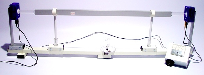
Rectangular metallic waveguide. Polarization e-field vertical.
With the wide side of the guide vertical no signal transmitted. Guide under cut-off
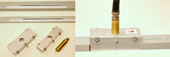
At left two slotted metallic waveguides with the respective carriages for holding the probe.
At right one of the probe carriages sliding on the guide
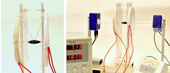
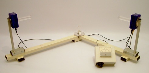
The set-up for the study of the Faraday effect.
The coils are in the Helmoltz configuration. Note the crossed transmitter and receiver polarizations